

Backend
Receive, process, deliver — on one compact unit.
The RepliCar Backend terminates up to eight radar links, supplies the modules through the same cables, runs the complete processing chain and provides results and raw data over standard interfaces. It combines an NVIDIA Jetson AGX Orin module with a carrier board that Wellenzahl developed specifically for RepliCar.
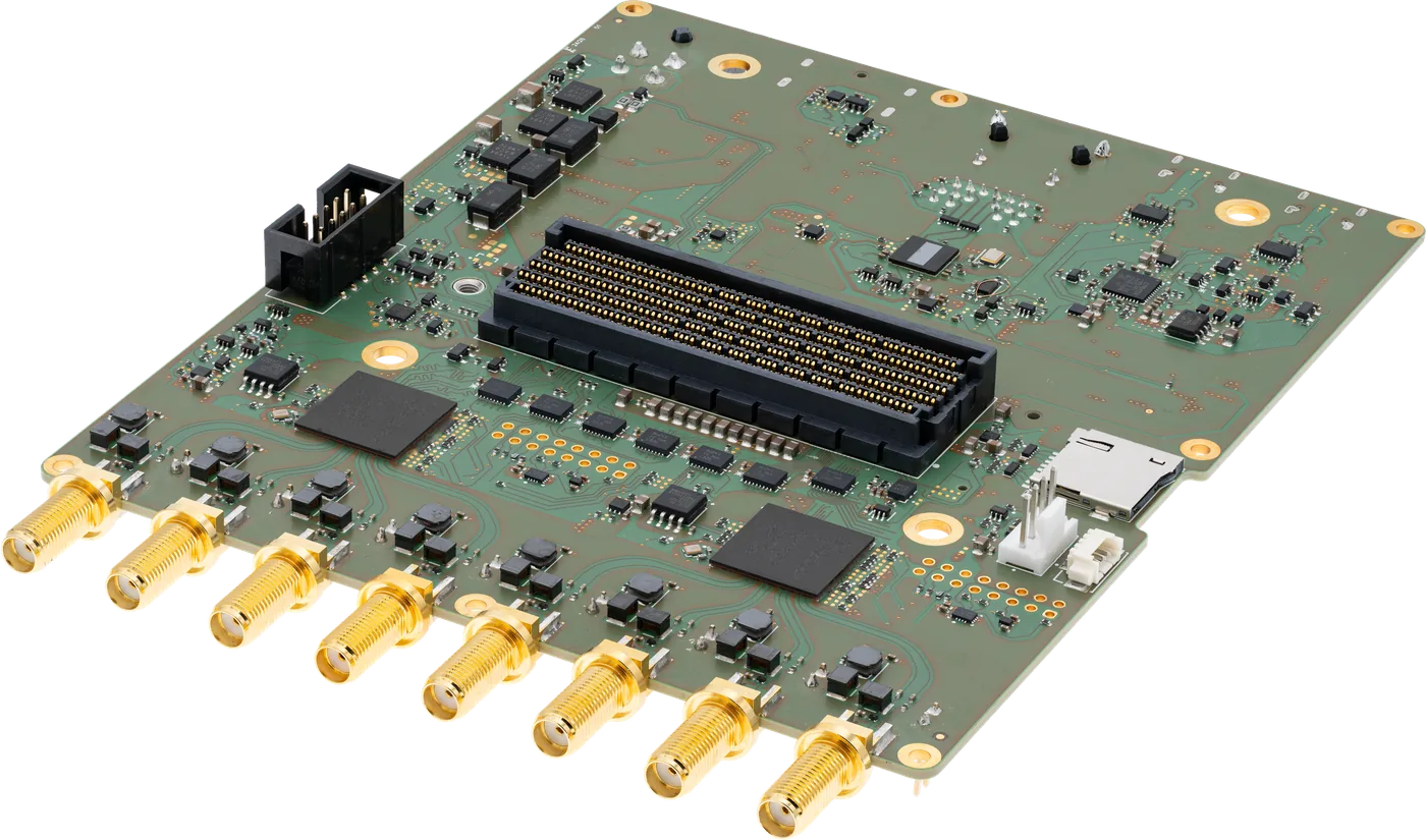
Developed for RepliCar. Nothing else required.
Instead of a development kit with add-on cards, the Jetson AGX Orin module sits on a carrier board designed by Wellenzahl. It brings everything a radar system needs: the inputs for the radar links, their supply, storage for recordings and fast interfaces to your infrastructure.
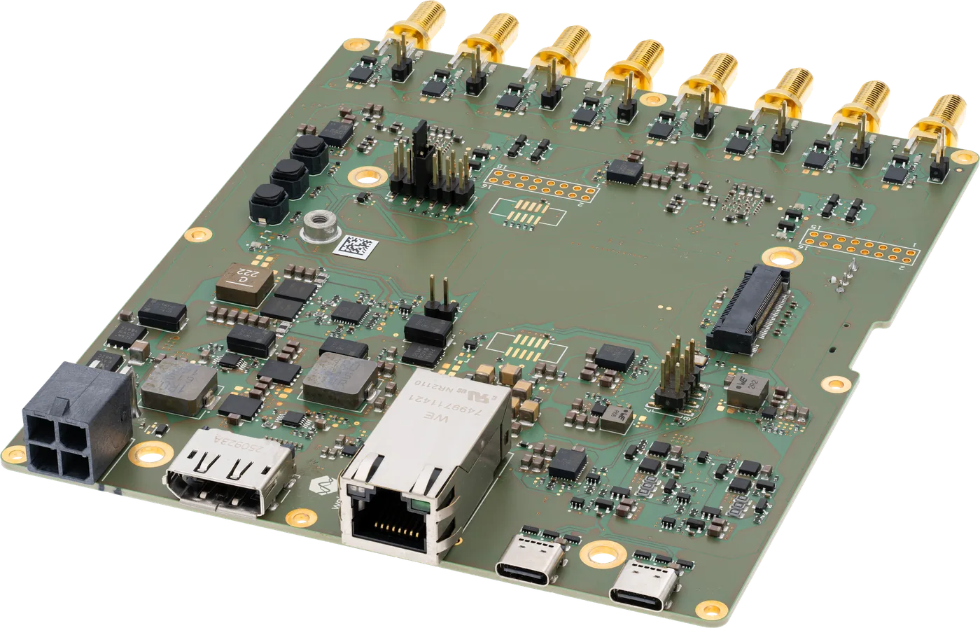
Eight radar inputs
Two A-PHY deserializers receive up to eight radar links. Raw data flows directly into the camera interface of the Jetson; control commands travel back to the modules on the same cables.
Supply over the radar cable
Every input supplies its module with 12 V over the coax cable — individually switchable, current-limited and with a status indicator per port.
Interfaces for your systems
10 Gigabit Ethernet for results and recordings, an M.2 NVMe slot for long recordings, USB-C, DisplayPort and microSD.
From the antenna to the point cloud — without detours.
Raw data reaches the memory of the Jetson without being compressed, packed into network packets or copied by the CPU. That keeps latency low and leaves the computing power for the signal processing.
Digitise
The transceivers sample the echoes with 12 bit; both streams are merged into one.
Transport
MIPI A-PHY over up to 15 m of coax, uncompressed.
Receive
The deserializers hand the streams to the camera interface of the Jetson.
Buffer
Radar frames arrive as standard V4L2 video frames — zero-copy.
Compute
Range-Doppler, detection, angle estimation, clustering, tracking — CPU or GPU.
Deliver
Point clouds and tracks via ROS 2, TCP or UDP; raw data in parallel.
Why C-PHY towards the Jetson? C-PHY carries about 2.28 bits per symbol on three-wire trios — roughly twice the bandwidth per pin of D-PHY — so the complete raw-data stream fits through the camera interface without running out of lanes.
Six stages. Every one switchable at runtime.
The complete chain runs in Rust on the Jetson. The CPU is sufficient for the Compact Cascade; CUDA takes over at full scale. Every stage can be switched during operation, from fast to high-resolution.
MIMO front end
The transceiver array delivers one coherent data cube per frame — chirps, channels and samples, phase-locked across all subarrays.
Range-Doppler
A two-dimensional FFT per channel produces range and velocity maps — the basis for detection and angle estimation.
Detection
An adaptive CFAR threshold finds targets reliably, even under varying noise and clutter.
Angle estimation
Selectable methods — from fast Bartlett to high-resolution Capon and MUSIC, plus the sparse methods OMP, ISTA and IHT — compute azimuth and elevation.
Point cloud and clustering
Detections are grouped into 3D objects, including heading and extent.
Multi-target tracking
An IMM tracker assigns stable IDs over time and smooths position and velocity.
Four layers, from the driver to the browser.
V4L2 radar driver
Linux kernelPresents radar frames as standard video frames with 12-bit raw data. Any V4L2-capable tool can capture them; one software image serves one to eight subarrays.
Radar control
radar-cliControls all connected modules, switches measurement profiles at runtime, records and replays raw data and serves the browser-based radar UI.
Signal processing
radar-processorRange-Doppler processing, CFAR detection, six angle-estimation methods — Bartlett, Capon, MUSIC, OMP, ISTA, IHT — DBSCAN clustering and IMM tracking, with a CUDA backend for large apertures.
Results and raw data
ROS 2 · TCP · UDP · V4L2Tracked point clouds and 3D bounding boxes for your application, ready for common tools such as Foxglove and RViz. Raw data stays accessible in parallel.
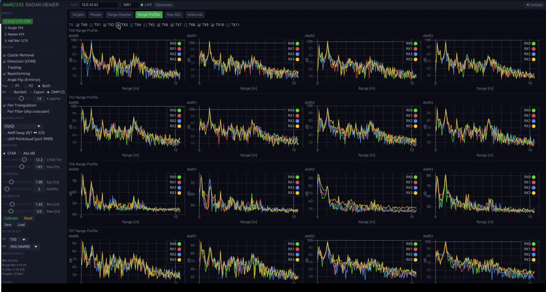
Three ways to work with RepliCar data.
Point clouds and objects
Subscribe to tracked point clouds and 3D bounding boxes via ROS 2, or receive them over TCP or UDP in your own software.
Switch processing at runtime
Select between the built-in processing methods during operation — for example from fast Bartlett to high-resolution Capon or MUSIC beamforming.
Live or recorded
Access the 12-bit raw data of every transceiver live, or record it and replay it into the processing chain as often as needed.
One detection, as an example
Typical content of a detection: position in 3D, radial velocity, signal strength, cluster and track assignment and a time stamp. The interface description documents fields, coordinate frame, units and time base.
// illustrative field names
{
  "frame": 18342, "t_ns": 1739871234567890123,
  "x_m": 12.41, "y_m": -1.87, "z_m": 0.36,
  "v_r_mps": -4.12, "snr_db": 21.7,
  "cluster_id": 3, "track_id": 17
}
Managed on the backend. Extended as you need.
Profiles define how the radar measures within the 76–81 GHz band: sweep bandwidth, chirp sequence, transmit scheme and frame rate. The backend distributes them to all connected modules and switches them during operation.
Tested profiles
Eight tested profiles from high range resolution to long range, ready for use on delivery.
Add profiles yourself
Define profiles for your scene and switch to them at runtime, without restarting the system.
Developed by Wellenzahl
On request, we develop and validate profiles for specific targets, ranges and velocities.
Measured on the backend.
| Configuration | Compute | Processing time per frame | Processing rate |
|---|---|---|---|
| Compact Cascade · 192 channels | CPU | 9–11 ms | 91–111 frames/s |
| Full Aperture · 3,072 channels | CPU | 39 ms | 25 frames/s |
| Full Aperture · 3,072 channels | GPU (CUDA) | ≈27 ms | ≈37 frames/s |
NVIDIA Jetson AGX Orin 64 GB. Processing time covers the computation per frame. End-to-end latency is measured from capture by the radar to the processed output; power consumption refers to the complete Full Aperture system including the backend.
At a glance.
| Compute | |
| Compute module | NVIDIA Jetson AGX Orin (benchmarks with 64 GB) |
| Operating system | Linux · NVIDIA JetPack 6.2 |
| Radar interfaces | |
| Radar links | 8 × MIPI A-PHY over coax |
| Module supply | 12 V per link · switchable · current-limited · status indicator |
| Control | Via the back channel of each link |
| Host interfaces | |
| Network | 10 Gigabit Ethernet (10GBASE-T, RJ45) |
| Storage | M.2 NVMe slot (Key M) · microSD |
| Further interfaces | 2 × USB-C · DisplayPort |
| Software and outputs | |
| Outputs | Tracked point clouds and 3D bounding boxes via ROS 2, TCP, UDP |
| Raw data | V4L2 video devices, 12-bit · recording and replay |
| Operation | Browser-based radar UI · profile switching at runtime |
| Supply | |
| Supply input | 12 V DC or USB-C Power Delivery |
| Power consumption | ≈95 W typical, 130 W peak for the complete Full Aperture system · backend alone: see datasheet |
Your algorithms on our data?
Request raw-data recordings, a live session on the system or a backend adapted to your interfaces.