

REPLICAR
From chirp to tracked 3D point cloud — in real time.
A real-time pipeline on a Jetson AGX Orin turns each AWR2243 MIMO frame into a tracked 3D point cloud — every stage runtime-switchable, scaling from a compact 4-chip stack to the full 8-subarray aperture shown here.
Two demonstrators. One architecture.
Cascaded AWR2243 front ends built and validated by Wellenzahl — from a compact four-chip stack to a cross-coherent 18-chip array.
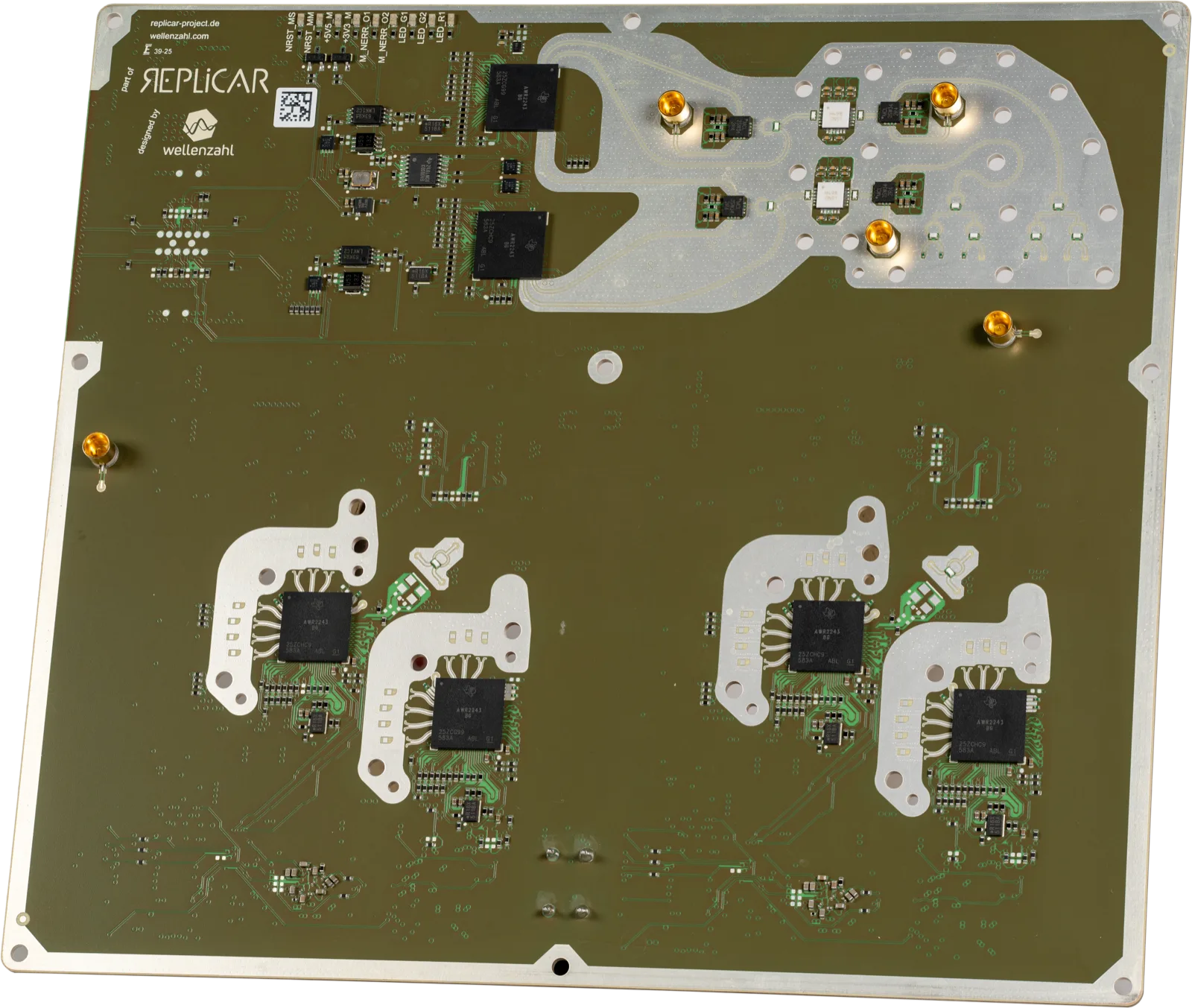
The four-chip cascade
- 4× AWR2243 — 12 TX / 16 RX RF channels
- Dedicated LO distribution, switchable between two master AWR2243
- Raw ADC data transfer for maximum signal-processing flexibility
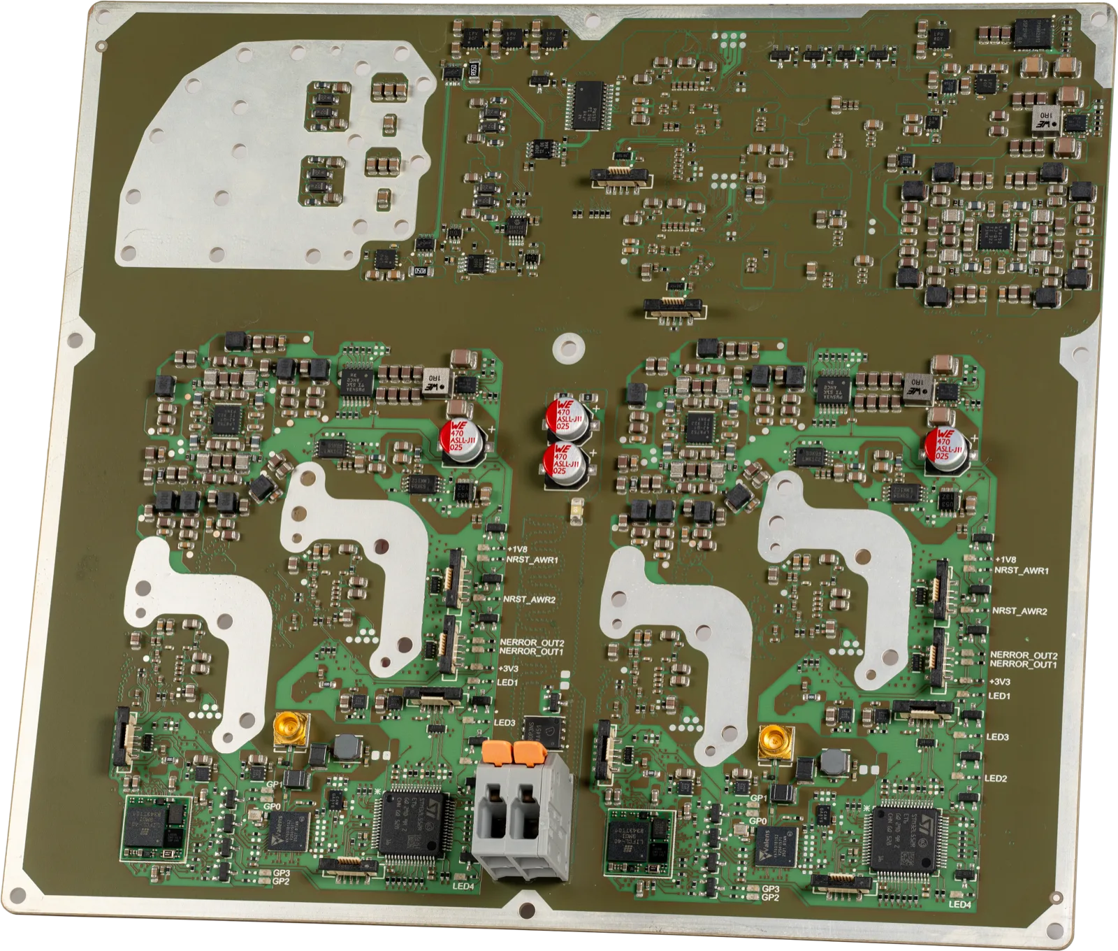
The cross-coherent array
- 16 + 2 AWR2243 in 8 subarrays → 48 TX × 64 RX = 3072 virtual antennas, cross-coherent
- Two cascade masters (master-master + master-slave) → flexible LO domains
- One STM32L5 per subarray with TI mmWave Link · dedicated supply or Power-over-A-PHY
One architecture. Tested profiles.
Subarrays, LO domains and chirp profiles are configuration, not redesign. Two builds are validated end to end — everything in between is a parameter set.
4 AWR · 2 subarrays
- MMICS
- 4 + 2 AWR2243
- TX × RX
- 12 × 16
- VIRTUAL ANTENNAS
- 192 · cross-coherent
- V4L2
- 4 × /dev/video0..3
- DATA RATE
- ~550 MiB/s @ 30 Hz
- COMPUTE
- CPU · Rayon/SIMD
- PIPELINE
- 9–11 ms · 91–111 Hz
16 AWR · 8 subarrays
- MMICS
- 16 + 2 AWR2243
- TX × RX
- 48 × 64
- VIRTUAL ANTENNAS
- 3072 · cross-coherent
- V4L2
- 16 × /dev/video0..15
- DATA RATE
- ~2.2 GiB/s @ 30 Hz
- COMPUTE
- CUDA · cuFFT
- PIPELINE
- < 30 ms · ~95 W
Everything in between is configuration: LO splits of 8/0, 7/1 or 4/3/1 run subarrays coherently or autonomously — up to 792 sliding subarray configurations on the same hardware.
Modular by design.
From a single subarray to the full 8-subarray system — architecture, firmware and software scale by configuration, not redesign. We serve any configuration on request.
Raw ADC data. Over 200 metres of range. No compromise.
Every subarray streams unprocessed IQ samples over automotive long-reach links into the Jetson's camera pipeline — landing in userspace as plain V4L2 devices.
Six stages. Every one switchable at runtime.
The full chain runs in Rust on the Jetson — CPU is enough for the compact profile, CUDA takes over at full scale. Every stage can be swapped live, from fast to high-resolution.
MIMO front end
The AWR2243 array delivers one coherent data cube per frame — chirps, channels and samples, phase-locked across all subarrays.
Range-Doppler
A 2D FFT per antenna produces range/velocity maps — the basis for detection and angle estimation.
Detection
An adaptive CFAR threshold reliably finds targets even under varying noise and clutter.
Angle estimation
Selectable beamforming — from fast (Bartlett) to high-resolution (Capon/MUSIC) — computes azimuth and elevation.
Point cloud & clustering
Detections are grouped into 3D objects, including heading and extent.
Multi-target tracking
An IMM tracker assigns stable IDs over time and smooths position and velocity.
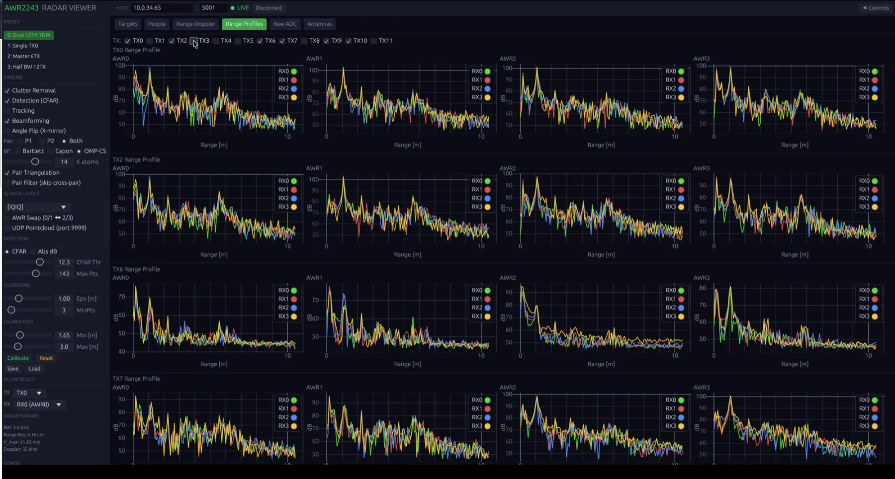
Live on the bench.
Configuration, live view and recording run in a web-based radar UI — straight against the Jetson.
Built within RepliCar.
Within the RepliCar project, Wellenzahl Radar- und Sensortechnik GmbH & Co. KG developed and validated high-resolution radar hardware and signal processing for robust environmental perception — from front-end electronics, firmware and synchronization to data acquisition and real-time evaluation, demonstrated live on functional demonstrator systems under realistic operating conditions.
Radar systems like this one?
HIGH-FREQUENCY ELECTRONICS · RADAR ARCHITECTURE · EMBEDDED SOFTWARE · MEASUREMENT
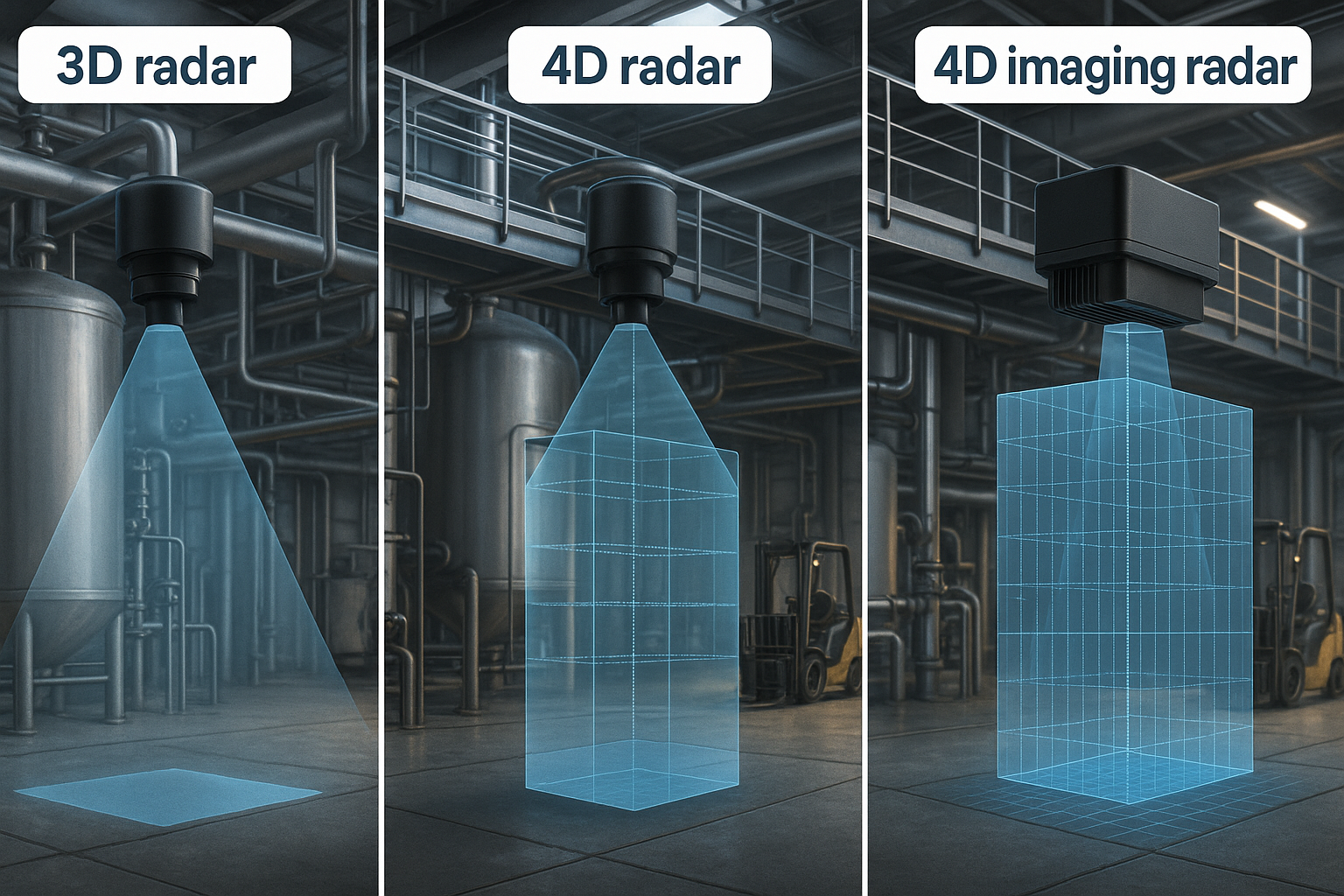
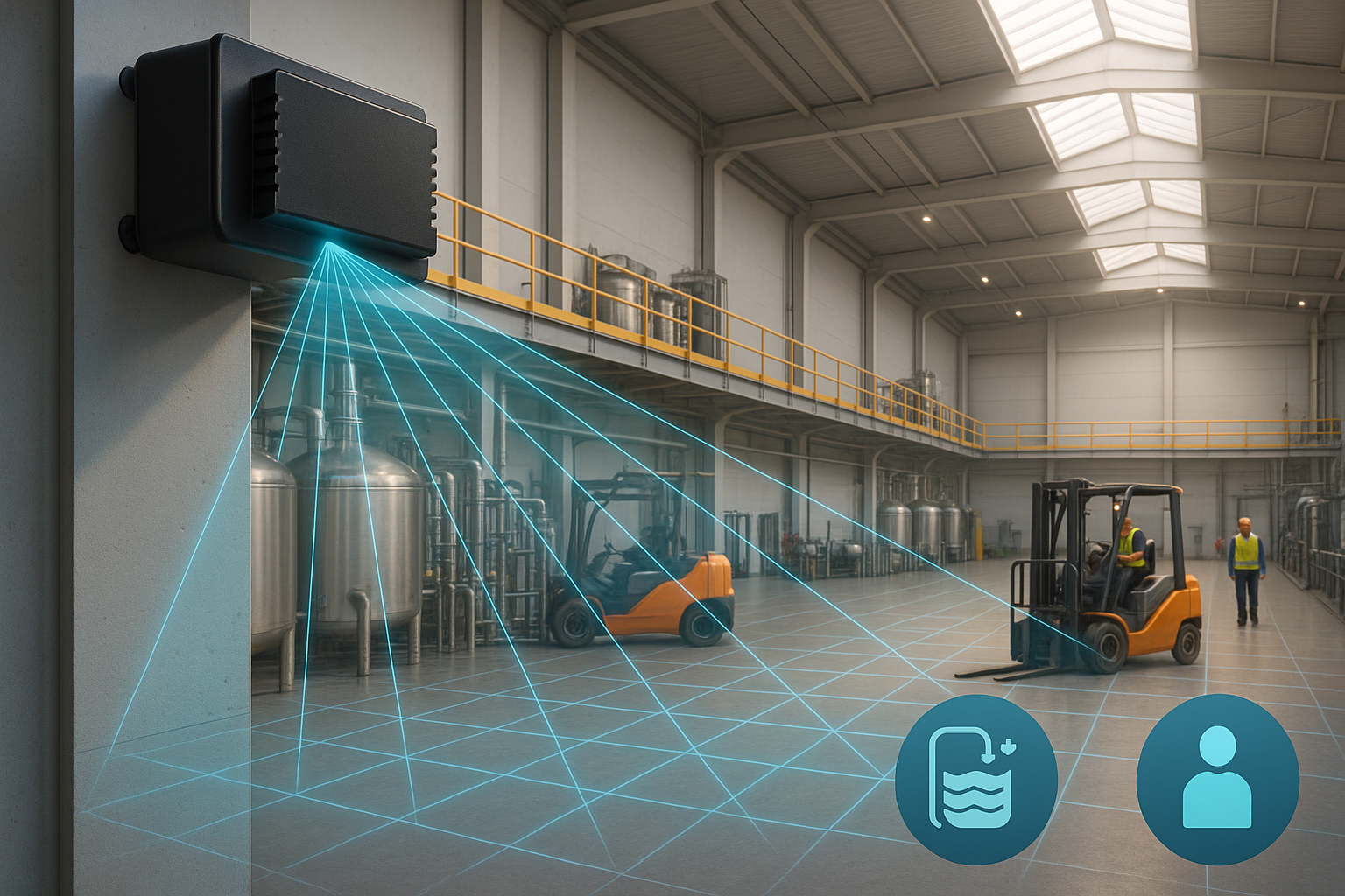
Imaging Radar
4D Radar
Radar sensors with multiple transmit and receive antennas (MIMO radar) are redefining performance standards in industrial sensing. By applying advanced beamforming and signal processing, these systems offer unmatched spatial resolution, precise object detection, and exceptional measurement stability—even in demanding environments with dust, steam, vibrations, or fast-changing conditions.
Beyond fill level measurement, multi-antenna radar excels in a wide range of applications, including object positioning, collision avoidance, flow monitoring, and presence detection. Whether in bulk material handling, smart factories, autonomous systems, or process automation, this technology ensures reliable and accurate data where conventional sensors reach their limits.
For industries aiming to enhance safety, efficiency, and data-driven automation, multi-antenna radar is the future-proof solution of choice.