RAPIDv3 - Base Platform
Overview:
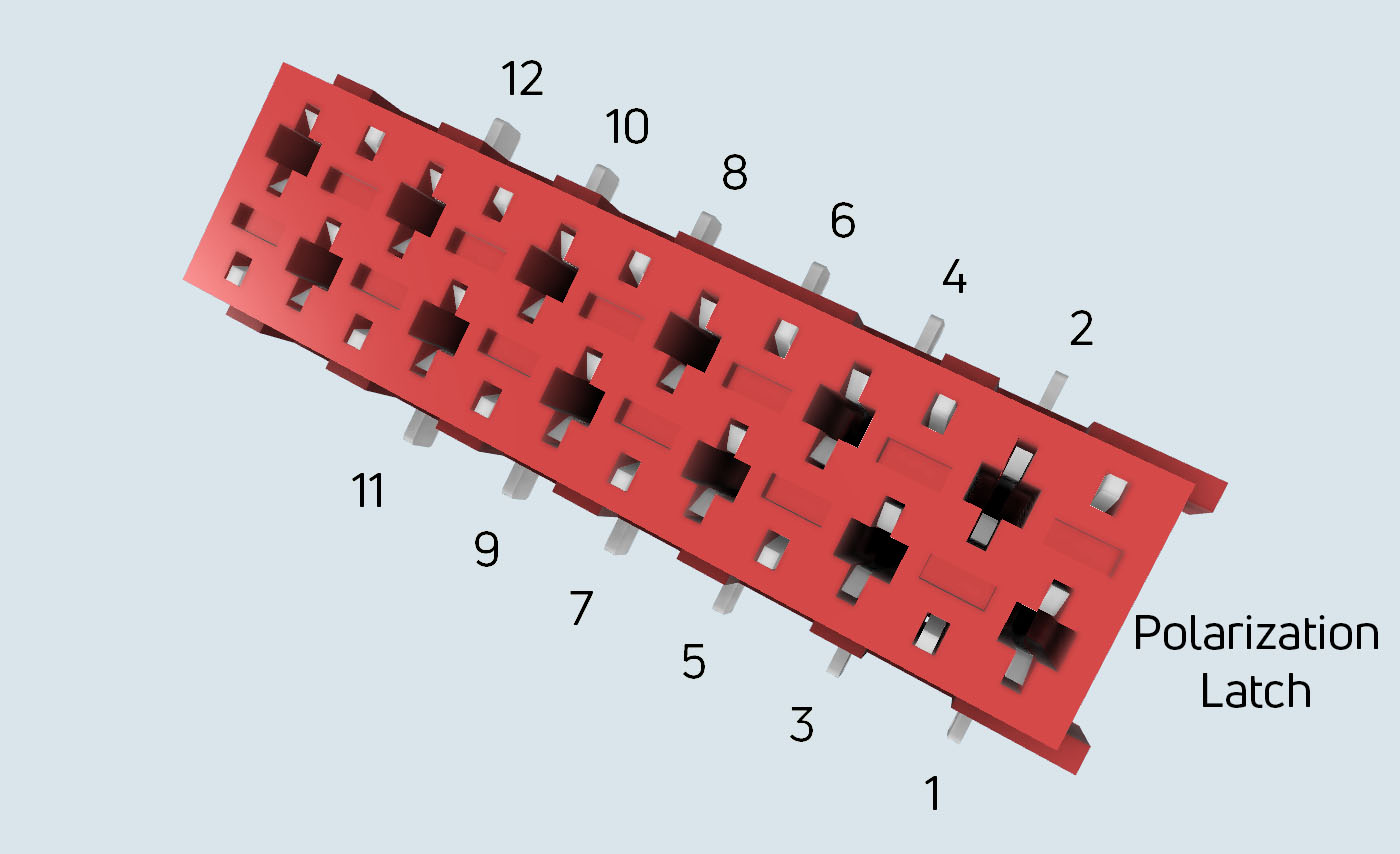
The shown 12-pin female connector is used at all RAPIDv3 compatible radar modules, whereas the pin assignment can differ for each of the radar modules.
The 12-pin female connector is applied to the radar modules whereas the male counterpart is connected e.g. on the Raspberry Pi rapid_v3_14u connector board. Additionally, a male connector for a standard flat ribbon cable is available.
Connector Part Numbers:
The connectors of the RAPIDv3 compatible radar modules and the counterparts are listed in the following table:
| Connector | Vendor | Part # | Description |
| 12-pin female SMD connector | Würth Elektronik | 690367281276 | Used at radar modules or as counterpart for flat ribbon cable connector |
| 12-pin male SMD connector | Würth Elektronik | 690357281276 | Used e.g. at Raspberry Pi connector board rapid_v3_14u |
| 12-pin male flat ribbon cable connector | Würth Elektronik | 690157001272 | Used for flat ribbon cable |
Basic Pin Description:
Most of the pins have several optional functions implemented which can be choosen individually at your order. The standard pin assignment for each RAPIDv3 compatible module is avilable upon request. At following table the basic configuration is shown:
| Pin # | Function | Description | Directon |
| 1 | Power | 1.8 or 3.3 or 5 V (radar module dependent) | Input |
| 2 | GND | Ground | Input |
| 3 | GPIO | main uasge: SPI_SCLK | Input |
| 4 | GPIO | main usage: I2C_SCL | I/O |
| 5 | GPIO | main_uasge: SPI_MOSI | Input |
| 6 | GPIO | main_usage: I2C_SDA | I/O |
| 7 | GPIO | main uasge: SPI_MISO | Output |
| 8 | GPIO | main usage: UART_TX | Output |
| 9 | GPIO | main usage: SPI_CS | Input |
| 10 | GPIO | main usage: UART_RX | Input |
| 11 | GPIO | main usage: GPO, data available for SPI | Output |
| 12 | GPIO | data available for SPI Output 12 GPIO main usage: GPI | Input |
Please note that the voltage level of GPIOs are always referred to the input voltage at the power pin.
Mechanical Dimensions:
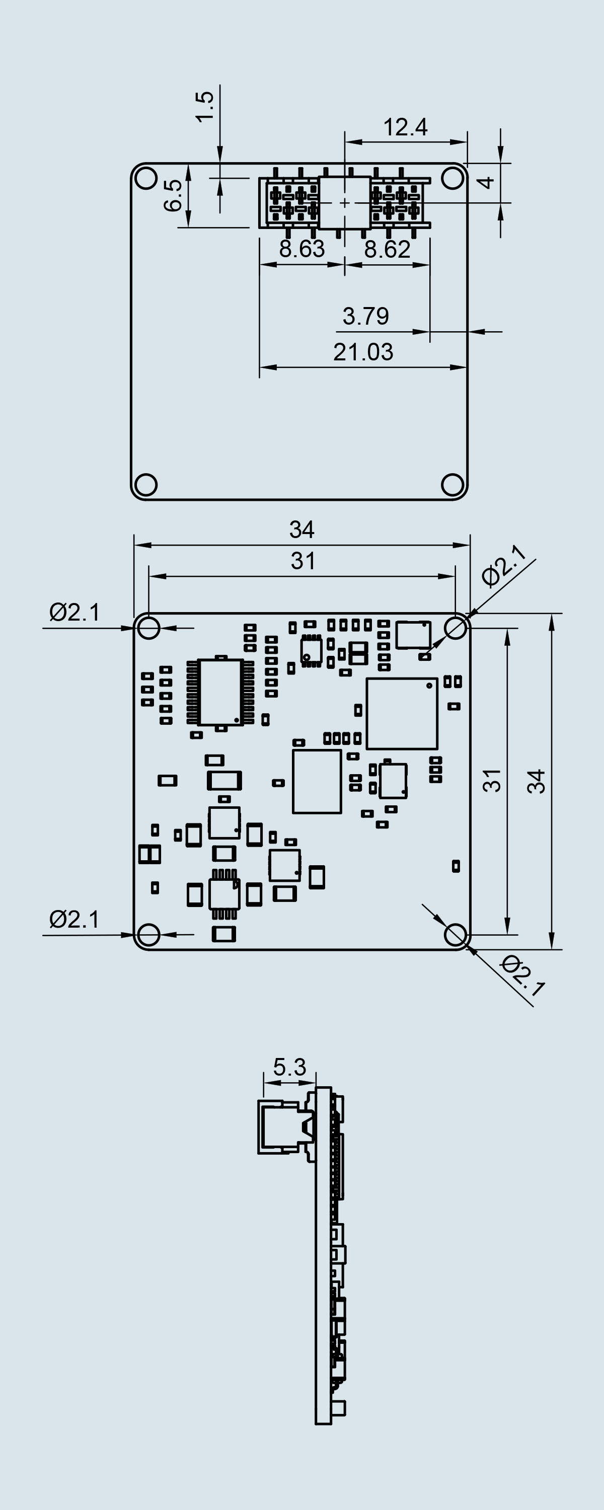
The RAPIDv3 compatible radar modules have a fixed PCB size of 34 x 34 mm². Four M2 screws can be used for PCB mounting. The phase center of the Tx / Rx antennas is basicly centered to the mid point of the PCB which makes the radar modules compatible for using a dielectric lens. The 2D drawing of the dimensions is shown in the image.


